| Author |
Topic: Setting power tube bias on Fender '65 Deluxe Reverb |
Bob Sykes
From:
North Carolina
|
 Posted 3 Feb 2024 9:29 am
 |
|
I'm trying to get my BF Deluxe back to gig-worthy reliability. It killed a power tube and some associated resistors. This is a '65 not re-issue.
I have replaced the dead components and the amp is working and actually doesn't sound too bad but the power tubes are red-plating at idle. I suspect that the bias is likely way too hot.
In order to minimize the chance of frying another 6V6 I would like to cut the bias way back before making any measured bias adjustments. So my simple question is: which way do I turn the bias pot to cool the tubes? I'd like to do this quickly after power-up so that I can make some measurements without risking meltdown. I have already replaced the screen and grid stopper resistors.
I have never set the bias on this amp but have no problem following the published procedure(s). I didn't find any that say which way to turn the bias pot.
_________________
Carters Starter, D10 8+7, SD10
ISO Sustainus Ad Infinitum |
|
|
|
Bill A. Moore
From:
Silver City, New Mexico, USA
|
|
|
|
Bob Sykes
From:
North Carolina
|
Posted 3 Feb 2024 1:08 pm
|
|
Thanks. I think I will ohm out the bias pot and check its rotational position with the amp out of the cabinet.
I'm wondering what that bias voltage would be with the power tubes removed. Nominal is -35V on the schematic (tubes in). I'm just trying to preserve those tubes if I can. Reading meltdown horror stories on the internet scared me. Fortunately I did not pack the amp for tonight's gig. I was poised to take it until I saw the plates glowing. 
_________________
Carters Starter, D10 8+7, SD10
ISO Sustainus Ad Infinitum |
|
|
|
Dave Mudgett
From:
Central Pennsylvania and Gallatin, Tennessee
|
Posted 3 Feb 2024 10:00 pm
|
|
Pull the power tubes, then measure the voltage at the control grid (pin 5 on a 6V6 - see this wikipedia article - https://en.wikipedia.org/wiki/6V6) relative to ground. It should be negative - the nominal value is -35 VDC. Now, with the tubes still out, rotate the pot and see which direction the voltage goes - a higher negative grid voltage reduces the plate current and thus cools off the tube. If everything is OK, this should be quite a bit higher in magnitude than -35. Now you can proceed to lower the grid voltage magnitude by turning the pot in the opposite direction.
Now - you could have some type of issue with the bias circuit. For example, if the bias filter capacitor is leaking DC, or the bias filter cap or resistor is out of spec, that could mess things up. So you may not be able to get a high enough negative voltage at the control grid. In this case, the bias circuit would need work. If this stuff is out of spec, I would suspect other things may be out of spec, and I'd get it to an experienced tech.
If that's all working correctly, I use a so-called 'bias meter', which inserts a 1 Ohm resistor into the circuit, and then measure the voltage across that resistor in millivolts. That mv reading corresponds to milliamps plate current through the 1 Ohm resistor. I tend to run my Deluxe Reverbs on the cool side - around 21-23 ma quiescent plate current.
There are other methods to set bias. Some people do it quite literally by ear - making sure they're nowhere near the red-plate area. There's the scope method, which increases the negative bias voltage until the crossover notch disappears, and then increases it a bit more to taste. In the end, I try to keep the tubes running as cool as possible, while still sounding good. For me, this is usually just moderately higher than just enough to lose the crossover distortion, which even without a scope, can be heard pretty clearly. |
|
|
|
Bob Sykes
From:
North Carolina
|
Posted 4 Feb 2024 1:58 pm
|
|
Thanks Dave, Without the power tubes in, bias was -35V. I dialed it back to -50V arbitrarily for troubleshooting purposes. I'll step it up once I go through some other things.
For some reason the bias filter cap is a 100uF 100V. I'll replace that when I get a 25uF. The 470 ohm bias resistor is north of 500 ohms. There are several other resistors throughout the power section that have increased in value. I had replaced the screen and grid stopper resistors during a previous meltdown fix.
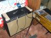
With bias pulled way back the plates do not glow. There's some high frequency oscillation on the output at low volume. Bottom trace is the input signal. I can chase that once I put the right cap in there and bias it properly.

This amp has had some output issues. Previously the output choke TR2 went open when I plugged in an external speaker cabinet. Replaced the choke and all was well except asymmetical clipping when pushed hard on the bench. This clipping issue may have preceded to choke failure. The amp Sounded pretty good though.
I may have to buy some resistors and begin wholesale replacement. I have access to large selection of carbon comp resistors at work but I have been screening them to find ones close to their nominal value. Most of them have drifted high just sitting in a drawer for a few decades.
Previously I just set the bias on this by looking at crossover distortion. I am going to try some alternate methods mentioned in Robinette's pages. I like science experiments.
_________________
Carters Starter, D10 8+7, SD10
ISO Sustainus Ad Infinitum |
|
|
|
Stephen Cowell
From:
Round Rock, Texas, USA
|
Posted 6 Feb 2024 1:52 pm
|
|
Post your exact schematic... some of these amps had balance instead of bias controls... the pot only controls one final.
They can be converted back or, adding a feature, you can have two pots, either one for each tube or one for bias and one for balance.
_________________
New FB Page: Lap Steel Licks And Stuff: https://www.facebook.com/groups/195394851800329 |
|
|
|
Bruce Derr
From:
Lee, New Hampshire, USA
|
Posted 6 Feb 2024 11:44 pm
|
|
100 uF 100 V is commonly used when replacing the bias filter cap in these amps. It is an improvement over the original 25 uF value. No reason to change it back (assuming the newer cap is good).
Stephen, I don't think Fender ever switched the Deluxe Reverb to the bias balance circuit. That was only done on the larger (6L6) amps. In any case, it didn't happen until a year or two into the silverface era, as far as I know. |
|
|
|
Dave Mudgett
From:
Central Pennsylvania and Gallatin, Tennessee
|
Posted 7 Feb 2024 9:02 am
|
|
I've never seen an original blackface Deluxe Reverb - or any 60s blackface amp, for that matter - with a bias balance. In fact, as Bruce mentions - I don't recall seeing a silverface DR with a bias balance. I have two '74/75 silverface DRs - both have a standard bias control.
If one is not worried about vintage resale value, I think dual pots, one for bias level, and another for bias balance, is a good idea from a performance point of view. Getting good matched NOS 6V6 tubes is getting harder all the time. Deluxe Reverb is one amp for which I simply will not use modern power tubes. I have tried, and I just have not found that they well tolerate the high B+ on a vintage Deluxe Reverb.
As far as vintage value goes - if one just floats the second pot, everything can easily be put back to stock by any purist potential buyer. For me, making mods like this would depend on just how pristine the amp is. This one has a replaced choke, and Bob sounds like he is well aware of getting good carbon comp resistors and is gonna replace out of spec components with proper replacements. In a situation like that, a floating bias balance pot would make sense to me. |
|
|
|
Bob Sykes
From:
North Carolina
|
Posted 7 Feb 2024 4:09 pm
|
|
Good stuff guys, thanks. Much food for thought. I've been doing some reading on Robinette's site and saw the bias cap upgrade which I'll leave in. Otherwise my amp matches the schmatic/layout on those pages.
https://robrobinette.com/AB763_Model_Differences.htm#Deluxe_Reverb
I made some measurement today and she's running hot. There's also an imbalance in cathode current(s). I haven't chased that yet (swapping tubes etc.)
With a plate Voltage of 415V:
Bias Cathode Current(s)
-44V 25/28 mA
-39V 43/43 mA
-35V 62/64 mA
I'll check the resistance of the OT. If that looks okay I'll swap in some new power tubes and see how those conduct. Beyond that, some probing and measuring I reckon. There's at least a few resistors that have drifted high. This might explain the quiescent imbalance as well as the asymmetrical distortion when pushed hard.
I'm getting less concerned with originality but would like to preserve what I can. I got it in the late '70s. The speaker had been changed by a previous owner. I replaced the filter caps, choke and some resistors already. The inside of the chassis is coated with a brownish film looks like cigarette tar or transformer outgassing, but Mains & OT appear original.
It has a few extra cool points with the short-lived rear chassis text "...Colombia Record" (No "u" in Colombia)
I like the bias balance control idea. It has been and will remain a "working" amp. I am might tempted to just cool bias it and take it out this weekend, with a back-up of course
_________________
Carters Starter, D10 8+7, SD10
ISO Sustainus Ad Infinitum
Last edited by Bob Sykes on 8 Feb 2024 10:41 am; edited 2 times in total |
|
|
|
Bill A. Moore
From:
Silver City, New Mexico, USA
|
Posted 7 Feb 2024 4:27 pm
|
|
Bob, if it has a bias balance, it can compensate for mismatched power tubes, (that's why the different tube readings). If you buy more, get a matched set.
My understanding is the "Vintage" tubes were close enough, that matching wasn't necessary.
I have made a run on a break to a local convenience store back in the day, and tested/bought a tube to get an amp working again. |
|
|
|
Bob Sykes
From:
North Carolina
|
Posted 7 Feb 2024 4:47 pm
|
|
Hi Bill, Its got a set of matched Groove Tubes in it now but they have seen some red-plating. I'm not trusting that they are still matched.
_________________
Carters Starter, D10 8+7, SD10
ISO Sustainus Ad Infinitum |
|
|
|
Bill Hatcher
From:
Atlanta Ga. USA
|
Posted 7 Feb 2024 8:21 pm
|
|
You can bias using current draw. Look up the Trainwrecknamp pages. Here is some info from there.
Conventional amplifier designs using fixed bias generally run 10-40 milliamperes per tube. Unsoldering the center tap and putting a meter in series can be extremely inconvenient on some amps. Trainwreck uses another system for measuring current, which does not require any wires to be disconnected in the amplifier.
Instead, the positive lead of the current meter will connect to the point of the center tap of the output transformer and the negative lead of the current meter should be connected to the plate pin of one of the output tubes. The plate pin is often Pin 3 in many tubes. Examples of tubes which would commonly utilize Pin 3: 6L6, KT66, KT 77, KT88, 5881, 6550, 6W6, EL34, 60A7. Some tubes, such as the EL84 (AC-30), 7591, 7027A, 7868 have the plate on a different pin.
However as we are measuring only ½ of the primary we will only be measuring the current for half the "push-pull" output. This method is accurate primarily because of the very low resistance of the meter which effectively shunts the winding of the output transformer and allows the total current to flow through the meter. Please bear in mind however that you are only measuring one half the output stage current. For example, if you want to set a 4 output tube amp to 30 milliamps per tube, first multiply 4 tubes times 30 milliamps to equal 120 milliamps total. Now since this method only measures one half of the total current you would adjust the bias until the meter reads 60 milliamps (one half of the 120 milliamp total). |
|
|
|
Bob Sykes
From:
North Carolina
|
Posted 8 Feb 2024 10:40 am
|
|
Hi Bill H, Thanks for the info. Currently I am measuring cathode current directly with a meter. Your post reminded me of exactly what I was measuring. I have corrected the above post to read "cathode current" rather than "Plate Current".
_________________
Carters Starter, D10 8+7, SD10
ISO Sustainus Ad Infinitum |
|
|
|
Ken Fox
From:
Nashville GA USA
|
Posted 10 Feb 2024 6:45 am BF Deluxe
|
|
The BF Deluxe and Deluxe reverb both use a 10K to ground off the bias pot Be sure that has not been changed out or drifted out of tolerance
A good site for checking the recommended bias is at:
https://robrobinette.com/Tube_Bias_Calculator.htm
Max plate dissipation recommended for 415 VDC plate voltage is 23.5 ma. If needed you change the 10K resistor value to cool the amp down. As the power supply is unregulated the plate voltage decreases with increases in cathode current. Good idea to re-calculate bias after each adjustment. I prefer to run the Deluxes at 19-21ma myself. Longer tube life for sure.
Be sure to check the 820 ohm negative feed back resistor.
Also does it have a Hammond replacement output transformer? Had those give positive feedback resulting in parasitic oscillation, due to the primary lead colors not identified same as Fender transformer.
Just some thoughts. Hope that helps a little. |
|
|
|
Bob Sykes
From:
North Carolina
|
Posted 11 Feb 2024 10:10 am Progress?
|
|
Hi Ken, Thanks your thoughts are very helpful. The bias pot resistor is not too far off and I seem to have a good range of bias voltage/current adjustment available. OTOH the 820 ohm neg feedback resistor is actually 82K and is marked as such 
Previously I had just "ballparked" the bias by looking at crossover distortion on the output waveform. Now with tube prices through the roof, I got a pair of bias (current) meters that insert in the cathode path via a tube socket adapter. I'm assuming the cathode current is about 5% more than the plate current. When adjusting bias, I am constantly measuring bias voltage, plate voltage and cathode current(s) real-time while keeping the plates at +415V by adjusting AC line variac.
I put a Hammond choke in this amp but assumed the output transformer was original. I'm not sure now. It has vinyl insulated wires where the old choke and transformers have cloth covered leads. More investigation needed on that.
This amp has some other issues. The power tube control grid signals have significantly different voltages. All of the resistors around the phase inverter have drifted too high. I will replace them, starting with the 5% spec. tolerance parts. The power tube grid stopper and 1W screen resistors are the only ones in spec.
I have measured dozens of unused carbon comp resistors in the "parts room" where I work and found none that are in tolerance. I'm buying new ones. 
The good new so far is the power tubes appear to be in good working order and the small difference in bias current balance is not the tubes but follows the amp when tubes are swapped.
I really appreciate the guidance and sanity checks you all have provided here. It's been several years since I bench dabbled in old amps. Fortunately, good (but not common) sense prevailed and I did not take this amp out to the gigs this weekend.
_________________
Carters Starter, D10 8+7, SD10
ISO Sustainus Ad Infinitum |
|
|
|
ajm
From:
Los Angeles
|
Posted 11 Feb 2024 11:42 am
|
|
Ken Fox: I may be missing something here.
You wrote:
"Max plate dissipation recommended for 415 VDC plate voltage is 23.5 ma."
Did you mean to say max plate CURRENT? |
|
|
|
Bill A. Moore
From:
Silver City, New Mexico, USA
|
Posted 11 Feb 2024 4:15 pm
|
|
Bob, I usually use carbon film resistors in my builds, but I put a 5E3 together for a friend who wanted it as close to 1957 as possible. He had already sourced a lot of the hardware, and found a beautiful chassis and cab, and even a period correct Jensen. I ordered 10 each for all the values in carbon comp, and was able to get all to the schematic spec with a lot of testing, but for him, it "looks" right!
(I even spent money on Jupitor, and Sozo caps with the marked "foil" end.) |
|
|
|
Bob Sykes
From:
North Carolina
|
Posted 21 Mar 2024 5:25 pm It's fixed
|
|
For those who may be interested I have this mostly resolved. The imbalance was caused by a broken control grid wire on the phase inverter tube socket. The insulation obscured the break and may have held the wires together enough to make it an intermittent connection. So the amp had been running as a Class A somewhat with one power tube doing all the work. That explains the red plating. It sounded OK like that but seemed to down on power
During the course of troubleshooting I ended up replacing all of resistors and caps downstream from the phase inverter coupling cap. I also discovered my power transformer is a 1973 model. That explains the thin film of transformer guts all over that end of the chassis.
The remaining challenge is preserving the 6V6 tubes. This amp has crazy high B+ voltages. At 120VAC line, the plate V is 455, when tubes are idling 26/30 mA with bias V -50.8V. I'm thinking of changing the rectifier to a 5V4 or 5U4 to lower the volts.
I played the amp on a gig all night last weekend and plan on using it again this weekend. It sounds great and has its old punch back  I do need to throttle it back a little though. I do need to throttle it back a little though.
_________________
Carters Starter, D10 8+7, SD10
ISO Sustainus Ad Infinitum |
|
|
|
Dave Mudgett
From:
Central Pennsylvania and Gallatin, Tennessee
|
Posted 21 Mar 2024 6:03 pm
|
|
| Quote: |
| The remaining challenge is preserving the 6V6 tubes. This amp has crazy high B+ voltages. At 120VAC line, the plate V is 455, when tubes are idling 26/30 mA with bias V -50.8V. I'm thinking of changing the rectifier to a 5V4 or 5U4 to lower the volts. |
So I assume your rectifier is 5AR4/GZ34. Yup, 455 VDC on the plates is really high for 6V6. As Ken says, voltage supply not regulated, so lower cathode current yields higher plate voltage anyway, so I think the 5U4 makes more sense in these amps, and that's what I use. I think Fender moved to 5U4 some time in the silverface era - yup, AB868 shows 5U4 - https://vintagefenderamprepair.com/pages/library-schematics-layouts
The plate voltage on my Deluxes are running a bit high on my Deluxes with 5U4 - I think 425 or 430 VDC at my typical 21-23 ma cathode current. I know I tried GZ34 years ago and concluded it was not a good idea. I know the idea is more plate current for more clean output, but only if the tubes can take it. I certainly wouldn't trust higher plate voltages with modern 6V6 tubes. |
|
|
|
Bob Sykes
From:
North Carolina
|
Posted 23 Mar 2024 12:24 pm
|
|
I would like to know if the rectifier heater winding changed in AB868 model xfrmr. The 5u4 is 3A filament where the Gz34 is only 2A. The xfrmr part number stayed the same but later model has a different 6V pilot light winding without center tap. My amp has this later circuit with resistors to simulate center tap,
I know how to figure out turns ratio on an unknown xfrmr but not current capacity. Warm wires are easy to check but windings and core temp no so much. I wouldnt want to kill a PT with overcurrent experiments anyway.
_________________
Carters Starter, D10 8+7, SD10
ISO Sustainus Ad Infinitum |
|
|
|
Bob Sykes
From:
North Carolina
|
Posted 29 Mar 2024 3:10 pm putting it back in service
|
|
I think I'm putting a bow on this one, at least for now. I learned a lot with this exercise. I swapped in a 5u4GB and without touching the bias pot measured the following:
Line=120VAC
GZ34 B+=462V Icathode 24/28mA
5U4GB B+=450V Icathode 22/26mA
I think the PT can handle the extra amp of filament current. Winding voltage is:
5.27VAC open circuit
5.14VAC with GZ34 installed
5.11VAC with 5u4GB
I played it for about 3 hours at a local bar jam session last night and I think it sounds great. The 5U4GB gives me a little peace of mind.
I'm tempted to try a bias balance pot as mentioned by Dave previously in this thread. Right now the tube with the lowest bias current surpasses the other tube when the drive level increases to 50mA and above. There also seems to be a little crossover distortion when the amp is driven to (sine) clipping.
Another experiment for another day....
_________________
Carters Starter, D10 8+7, SD10
ISO Sustainus Ad Infinitum |
|
|
|
Dave Mudgett
From:
Central Pennsylvania and Gallatin, Tennessee
|
Posted 29 Mar 2024 5:47 pm
|
|
I thought I had replied to your previous post about the filament current of 5U4 vs 5AR4/GZ34, but I guess I was recovering from the road still and forgot to post it.
If you look at the schematics for AB763 vs AB868, you'll see that AB763 calls for GZ34 rectifier with the 125P23B power transformer, and AB868 calls 5U4 rectifier with the same 125P23B power transformer. I used a 5U4 with my old blackface '65 Deluxe Reverb for at least 20 years without any incident to the power transformer. I did blow the output transformer - playing pedal steel into an external 8 Ohm JBL D130F, in the middle of a gig. The bass player tapped me on the shoulder and pointed to smoke coming out of the 2nd input jack, argh. I suspect that steel did tax the output transformer quite a bit more than I ever did with guitar. But I never had any type of issue with the power transformer on any DR. I actually found a '68 DR output transformer for the '65 - I think it was a bit more stout, but it was exactly the same number.
I never measured the filament voltage under load for different rectifiers, but I think it's good that you did that. That's not much extra drop - it doesn't surprise me, but it's good to know. I believe Fender, unlike some other vintage amps, significantly over-specified transformers, both output and power. Fenders are well known to be much more tolerant of moderate speaker load mismatches than, let's say, vintage Marshalls. I still generally am firm about presenting the correct speaker load, even for a Fender. But I would never think about a mismatched load on a vintage Marshall.
I think adding a floating bias balance pot is a reasonable thing to do if the amp is not a museum piece. Easy enough to turn back to stock. I've had a few amps with that mod. I don't think it's a big deal difference unless the power tubes really drift apart from each other. I actually have a bias balance, with a digital millivolt meter mounted on a repro back panel, on my '66 Vibrolux Reverb. The bias is adjustable from outside the chassis, but the balance is only adjustable inside the chassis. I had the same thing on my old '65 DR, which I traded about 11 years ago. I now run a pair of '74 silverface DRs when I use them for steel. |
|
|
|